Intra-Oral Temperatures During Unlocking of Smileloc Retained Restoration Using Smilekey

Executive Summary
The RODO Smilekey quickly, precisely and repeatably unlocks Smilelocs through induction heating and the resulting temperature increases reached in the crown (6.7℃ – 13.9℃), abutment (10.1℃ – 13.5℃), and implant (3.7℃ – 5.8℃) during the unlocking procedure stay within established safety limits. This is true for both normal and abnormal (user-error) Smilekey application. These temperatures are comparable to increases produced during common dental procedures, including light curing of composite resins 1 and teeth whitening procedures 2 . In all cases, the temperature rise of the implants was below 6℃, which is below the threshold temperature for thermal damage to bone tissue. The greatest temperature rise happened in the PFM crowns and, even if there is a need for a second consecutive activation, the Smilekey can be safely reactivated on these same crowns after a 2-minute cool down per RODO Medical’s Instructions for Use as temperatures stay below established safety limits even during reactivation.
Introduction
The FDA-approved RODO Smilekey® is the induction remover device for Smileloc® in the RODO Abutment System. During the unlocking procedure, the Smilekey Tip is placed near the restoration and delivers induction energy to the Smileloc, heating the Smileloc to its activation temperature and causing it to change from a locked to an unlocked configuration. The implant, abutment, and restoration can also heat up due to either induction, thermal conduction or a combination of both. These parts must not exceed established temperature limits in order to protect the oral tissues they have direct contact with. However, the temperature change experienced by the implant, abutment, and restoration depends on the materials selected for each component. Therefore, the purpose of this study was to evaluate the temperature rise on different implant, abutment, and restoration materials during the unlocking procedure using the RODO Smilekey to ensure that the temperature changes did not exceed established safety limits.
Background
Induction heating is a non-contact method for directly heating electrically-conductive materials. By immersing the induction target in an alternating magnetic field, the flow of free charge carriers (e.g. electrons) is induced and loops of electrical currents Intra-Oral Temperatures During Unlocking of Smileloc-Retained Restoration Using Smilekey Author: Chase S. Linsley, PhD EXECUTIVE SUMMARY The RODO Smilekey quickly, precisely and repeatably unlocks Smilelocs through induction heating and the resulting temperature increases reached in the crown (6.7℃ – 13.9℃), abutment (10.1℃ – 13.5℃), and implant (3.7℃ – 5.8℃) during the unlocking procedure stay within established safety limits. This is true for both normal and abnormal (user-error) Smilekey application. These temperatures are comparable to increases produced during common dental procedures, including light curing of composite resins 1 and teeth whitening procedures 2 . In all cases, the temperature rise of the implants was below 6℃, which is below the threshold temperature for thermal damage to bone tissue. The greatest temperature rise happened in the PFM crowns and, even if there is a need for a second consecutive activation, the Smilekey can be safely reactivated on these same crowns after a 2-minute cool down per RODO Medical’s Instructions for Use as temperatures stay below established safety limits even during reactivation. www.rodomedical.com | Page 2 RODO UNIVERSITY known as eddy currents are generated (Figure 1A) 3 . However, electrons can lose energy due to inelastic collisions with atoms or ions in the conducting material that transfers to the lattice as vibrational energy. This process is known as Joule heating and is dependent on the material’s properties.
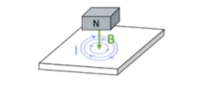
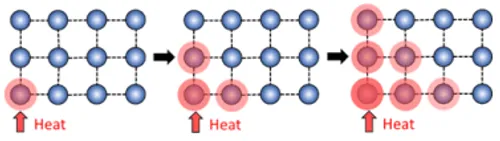
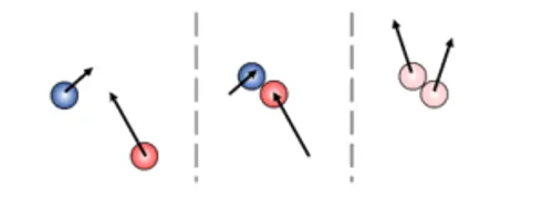
Figure 1. Heating diagrams: (A) Induction heating occurs in electrically conductive materials exposed to a magnetic field, B, coming from a magnet’s north pole, N. This induces the flow of free charge carriers and loops of electrical currents, I, are generated. These charge carriers can lose energy due to inelastic collisions with atoms or ions in the conducting material that transfers to the lattice as vibrational energy. (B) Conduction heating by lattice vibration occurs by highly energetic atomic movements being transferred through the series of bonds in a solid material until all atoms are vibrating with the same energy. (C) Conduction by particle collisions occurs in solids with free electrons, which are not bound to any particular atom and can freely move about the solid (e.g. metals). As the electrons undergo a series of collisions, the faster electrons give off some of their energy to the slower electrons.
Electrically non-conductive materials are not directly heated by exposure to an electromagnetic field. Instead, heat can be transferred to these materials through conduction. The flow of heat between materials depends on the materials’ thermal conductivities. Thermal conduction in solid materials is made possible by the propagation of lattice vibrations (Figure1B) and the movement of electrons (Figure 1C). The heat transfer efficiency of a given material depends on several factors, including the molecular arrangement, bond types between atoms, atomic species present and their respective mass. The flow of heat between materials also depends on the thermal contact conductance. Thermal contact conductance is a measure of how easy it is for a temperature gradient to promote heat flow from one material to another and it is limited by the fact that even the smoothest interfacing surfaces only have a few discrete locations where contact is made 4 . Consequently, heat transfer at interfacing surfaces is determined by both conduction through contact locations as well as conduction through the interstitial medium.
Dental implant restorations are made of multiple material types in contact with one another and range from thermal-conducting to thermalinsulating. Metallic bonding between metal atoms produces a sea of delocalized electrons that are highly mobile, imparting thermal conductivity. However, irregularities in the atomic structure and differences in chemical composition introduce scattering centers for conducting electrons and reduce thermal conductivity. For nonmetals, lattice vibrations called phonons are the primary conductor of heat and are sensitive to structure. For instance, polycrystallineceramics can be either thermal-conducting or thermal-insulating where simple crystal structures comprised of strong bonds between smaller atoms produce thermally conductive ceramics. Similarly, polymeric materials (e.g. acrylic resins) that are highly crystalline have greater thermal conductivities than their amorphous counterparts. Additionally, heat flow in polymers is further complicated by the number of mobile structural units, such as side groups, chain segments, and macromolecular chains 5 . The differences in heat transfer and susceptibility to induction heating mean that the materials selected for an implant restoration will impact the temperature rise experienced by each component of the system during an activation. Therefore, thermal analysis of commonly used materials for dental restorations is required to establish the safety of unlocking the Smileloc with the RODO Smilekey.
| Maximum Temperature Rise (Δ℃) | ||||
|---|---|---|---|---|
| Duration | Abutment (Metal) | e.max, Zr, PFM Crown (Porcelain) | Acrylic (Plastic) | Implant (Metal) |
| t < 1 s | 37 | 43 | 49 | - |
| 1 s ≤ t < 10 s | 19 | 29 | 34 | - |
| 10 s ≤ t < 1 min | 14 | 19 | 23 | - |
| 1 min ≤ t | 11 | 11 | 11 | 10 |
Tests were conducted to measure the induced heating of common dental materials by Smilekey following RODO Medical’s Instructions for Use as well as deviations due to user error. The allowable temperature limits were established by IEC 60601-1 and Eriksson & Albrektsson (1983) 6 and are summarized in Table 1.
Materials and Methods
The abutment system configurations tested included several commonly used dental restoration materials – lithium disilicate (Ivoclar Vivadent e.max), porcelain fused to metal (PFM), zirconia (Zr), and acrylic – as well as titanium copings and abutments (S-, M-, and D-series, RODO Medical, San Jose, CA). Commercially available titanium implants (Bone Level implants Ø 4.1 mm, Straumann, Basel, Switzerland) were used
Fiber optic thermometers (Fotemp4, Optocon) were used for temperature measurements as it is immune to electromagnetic interference produced by the induction coil. The experimental test setup is illustrated in Figure 2 and mimics the oral anatomy. A gelled saline solution was prepared per ASTM F2182-11a to simulate oral tissue. Temperature sensors were attached to the crown using a conductive epoxy as well as placed near (within 2 mm) the abutment and implant, which were both submerged in the gelled saline solution. The RODO abutment restorations were locked onto the abutment/implant assembly with a Smileloc. The Smilekey was placed over the restoration and activated.
Several scenarios were tested, including: a) measuring the induced heating of components in RODO abutment restorations caused by Smilekey activation following the Instructions for Use. The appropriate activation setting for acrylic restorations is 5 seconds (s) and for non-acrylic restorations it is 8 s. b) Measuring the temperature change caused by consecutive activations. The Instructions for Use recommend initiating a second activation 2 minutes after the first activation ended in the event that Smileloc fails to unlock. The PFM RODO abutment restoration was tested because it was the configuration with highest temperature rise during Smilekey activation. c) Measuring the temperature change of an adjacent implant with a cementable abutment during RODO abutment activation. The experimental setup was modified by placing a RODO abutment and OEM abutment restoration next to each other in the gelled saline such that the fluid line mimicked the oral anatomy. The rise in temperature of the OEM abutment restoration was recorded during activation of the neighboring RODO abutment assembly using the Smilekey. d) Measuring the induced heating resulting from deviations from the Instructions for Use. First, to assess whether a Smilekey activation on a cementable abutment restoration as a result of user error would cause harmful temperatures increases, the RODO abutment restoration was replaced with an OEM abutment and Smilekey was placed over the restoration and activated for 8 s. Second, the temperature change in acrylic dentures was measured while using the wrong Smilekey activation setting (8 s instead of 5). In all the above scenarios, each configuration was activated six (6) times.
All activation runs were conducted at room temperature (20℃). However, in a clinical setting, the temperature change required to activate Smileloc, which has maximum activation temperature of 63℃, from body temperature (37℃) is 26℃ (ΔT = 63℃ − 37℃). Therefore, Smilelocs with activation temperatures normalized to room temperature were manufactured for this study. The study Smilelocs needed to reach 46℃ to achieve the required activation temperature change (ΔT = 26℃), which was verified using a water bath with an immersion circulator and thermocouple.
RESULTS & DISCUSSION
Figure 3 shows the average temperature rise for the components in bicuspid and molar restorations with an e.max crown, using Regular and Wide RODO abutments respectively. Heating continues for up to 10 s after Smilekey activation has finished. The maximum temperature reached in the bicuspid crown was 9.5℃ (±0.5℃) and 6.7℃ (±0.2℃) in the molar crown. Lithium disilicate glass ceramics are popular restoration materials due to their optimal aesthetics as well as excellent strength and durability. This is due to its microstructure – 70% crystalline but its many randomly oriented, needle-like crystal structures help arrest the propagation of cracks through the material 7 . These irregularities in the atomic structure introduce scattering centers for phonons and lower thermal conductivity. As such, e.max crowns act as a thermal insulator.
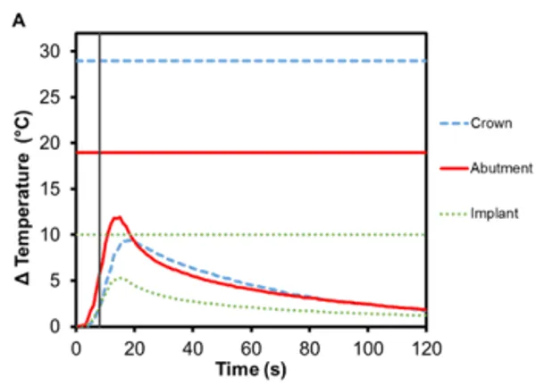
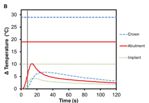
Figure 3. Change in temperature of (A) Regular and (B) Wide abutment, implant and lithium disilicate crown as a function of time, where time zero represents the onset of activation induction energy. The vertical line at 8 s represents the end of the activation. The horizontal lines indicate maximum allowable temperature increases for 1 s ≤ t < 10 s tissue contact times for both the crown and abutment, and over 1 min tissue contact time for the implant. In both series, the max
The greatest temperature change occurred in the abutment, which has direct contact with the Smileloc sleeve during activation in order to unlock. Specifically, the Regular abutment reached a maximum temperature rise of 11.9℃ (±0.7℃) and the Wide abutment’s maximum temperature rise was 10.1℃ (± 1.0℃). These abutments are screwed into an implant, which experiences a maximum temperature change of 5.3℃ (±0.2℃) and 4.4℃ (±0.6℃), respectively. Both the abutment and the implant are fabricated out of commercially pure titanium, which inherently has a lower electrical (resistance = 0.554 Ω∙mm2 m1) and thermal conductivity (22 Wm-1K -1 ) 8,9. Consequently, limited induction heating of the titanium components is detected and the transfer of heat from component-to-component is not efficient.
Zirconia is another commonly used ceramic for dental restorations due to its excellent aesthetics and mechanical properties, which it owes to phase transformation toughening 10,11. As seen in Figure 4, there is an increase in temperature for zirconia crowns during Smilekey activation and the heating continues for up to 10 s after it has finished. The maximum temperature reached in the bicuspid crown was 7.4℃ (±0.5℃) and 7.1℃ (±0.2℃) in the molar crown. Again, the greatest temperature change was measured in the abutment – Regular abutment increased 11.1℃ (±0.7℃) and Wide abutment also increased 11.1℃ (±1.0℃) – and little temperature rise was measured in the implant: 5.8℃ (±0.2℃) and 3.7℃ (± 0.3℃), respectively. Similar to e.max crowns, zirconia acts as a thermal insulator.
PFM crowns have been considered the gold standard for dental restorations due to their durability and extremely high 10-year success rates (>90%) 12,13 . They have a metallic substructure commonly made of precious metal alloys, often gold but other metals have been used as well, including platinum and palladium 14. The substructure is covered with porcelain veneer, which is most often a silica-based ceramic that mimics the coloring and shading of natural teeth, is resistant to chemical attacks, does not deteriorate with time, and is biocompatible 15. The alloy used in the PFM crowns for this study was Argedent 505 – a white, high noble alloy composed of 50% gold, 36% palladium, 7.4% indium, 5% silver, and 1.5% gallium. As seen in Figures 4A and 4B, the presence of gold in the crown resulted in a greater temperature change then the other crown materials tested. The bicuspid PFM crown had a 13.9℃ (± 0.4℃) increase and the molar PFM crown had a 12.9℃ (±0.5℃) increase. Gold is a substantially better conductor of heat (297 Wm-1K -1 ) than titanium and gold nanoparticles have also been shown to undergo Joule heating when exposed to electromagnetic radiation 16. The exact contribution that conduction versus induction heating had on the final temperature rise was outside the scope of this study, but both were likely to have contributed. It was also found that there was a slight increase in the maximum temperature rise of the abutments: 12.0℃ (± 0.4℃) for Regular and 13.5℃ (±0.7℃) for Wide abutments. Because the highest temperature rises in the crowns and abutments occurred with this configuration, a safety test was conducted to confirm that reactivation of Smilekey after a 2 min cool down as specified in RODO Medical’s Instructions for Use did not produce dangerous increases in temperature in the event that the first activation failed to unlock Smileloc. The results show that the maximum temperature rise was still below the set safety limits for both activations but that the temperature rises were greater during the second activation for all components (Figure 5C).
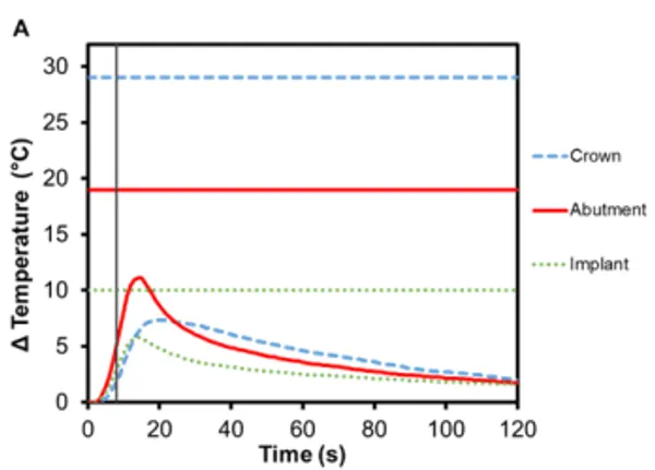
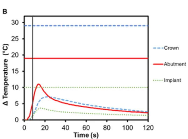
Figure 4. Change in temperature of (A) Regular and (B) Wide abutment, implant and zirconia crown as a function of time, where time zero represents the onset of activation induction energy. The vertical line at 8 s represents the end of the activation. The horizontal lines indicate maximum allowable temperature increases for 1 s ≤ t < 10 s tissue contact times for both the crown and abutment, and over 1 min tissue contact time for the implant. In both series, the max
Implant-supported dentures can also be secured using Smilelocs with Regular Multi-Unit abutments. Dentures are made of a tissue-colored acrylic base, and either porcelain or natural teeth-colored acrylic that are attached to the base. Polymethyl methacrylate has historically been the most popular acrylic resin used to fabricate dentures, and at room temperature these acrylic resins are hard and glass like. Activation using Smilekey’s 5 s setting shows little-to -no temperature increase in the denture (0.4℃ ± 0.1℃) and there is a decrease in the maximum temperature rise experienced in the abutment and the implant: 6.2℃ (±0.3℃) and 2.5℃ (±0.2℃), respectively (Figure 6A). Even if the 8 s activation setting is used in error, there is minimal temperature increase in the denture: 0.7℃ ±0.1℃ (Figure 6C). Even acrylic dentures that utilize titanium bars experienced little increase in temperature. After 5 s activation, the maximum temperature increase for denture crown was 3.4℃ ±0.2℃ and the titanium bar was 4.9℃ ± 0.4℃ (Figure 6B). If the 8 s activation setting is used in error, the maximum temperature increase in the dentures was 5.2℃ ±0.5℃ and the titanium bar was 7.7℃ ±0.6℃ (Figure 6D). Overall, the temperature profile remained below set safety limits. Additionally, the risk of damaging the denture material is negligible considering the glass transition temperature for polymethyl methacrylate-based resins is above 100℃ 17.
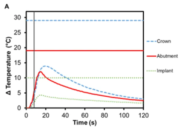
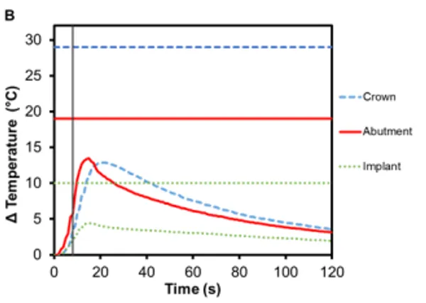
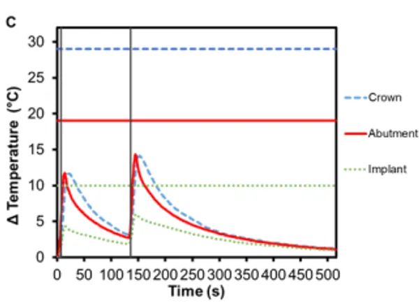
Figure 5. Change in temperature of (A) Regular and (B) Wide abutment, implant and PFM crown as a function of time, where time zero represents the onset of activation induction energy. The vertical line at 8 s represents the end of the activation. The horizontal lines indicate maximum allowable temperature increases for 1 s ≤ t < 10 s tissue contact times for both the crown and abutment, and over 1 min tissue contact time for the implant. In both series, the maximum temperature rise was less than the maximum allowable temperature for each component of a RODO Abutment System. (C) The change in temperature of a Wide abutment with a PFM crown as a function of time after two sequential 8 s activations with a 2-min cool down in-between show that the maximum temperature rise was below the set safety limits during and after both activations. The temperature rises were greater during the second activation for all components.
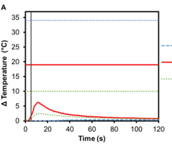
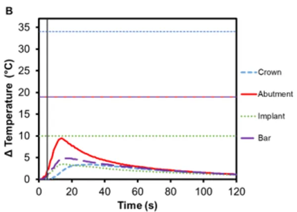
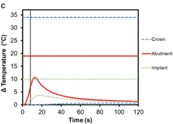
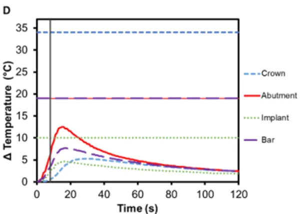
Figure 6. Change in temperature of (A) an acrylic denture on Regular Multi-Unit abutment and (B) a titanium-bar-supported acrylic denture on Regular Multi-Unit abutment as a function of time, where time zero represents the onset of activation induction energy. The vertical line at 5 s represents the end of the activation. The horizontal lines indicate maximum allowable temperature increases for 1 s ≤ t < 10 s tissue contact times for both the crown and abutment, and over 1 min tissue contact time for the implant. The change in temperature of (C) the acrylic denture configuration and (D) the titanium-bar-supported acrylic denture configuration as a function of time when the wrong setting is selected for Smilekey (i.e. user error). The vertical line at 8 s represents the end of the activation. During both the activation settings, the maximum temperature rise was less than the s represents the end of the activation. During both the activation settings, the maximum temperature rise was less than the maximum allowable temperature for each component of the RODO Abutment System.
The risk of thermal injury to a patient during 8 s Smilekey activation applied to a cementable abutment restoration as a result of user error is extremely low as shown in Figure 7A. The maximum temperatures observed for the crown, abutment and implant are all below their respective safety limits. The maximum temperature change was measured in the abutment (7.0℃ ±0.2℃) followed by the crown (6.8℃ ±0.1℃) and finally the implant (4.7℃ ±0.1℃). Additionally, the temperature change of an implant neighboring a RODO restoration that is undergoing activation was measured. It can be seen in Figure 7B that there is little-to-no temperature rise in the neighboring restoration – the maximum temperature increase for all component of the restoration was less than 2℃ – and importantly, there is also no temperature increase in the oral tissue adjacent to the Smilekey even when the 8 s activation setting is used.
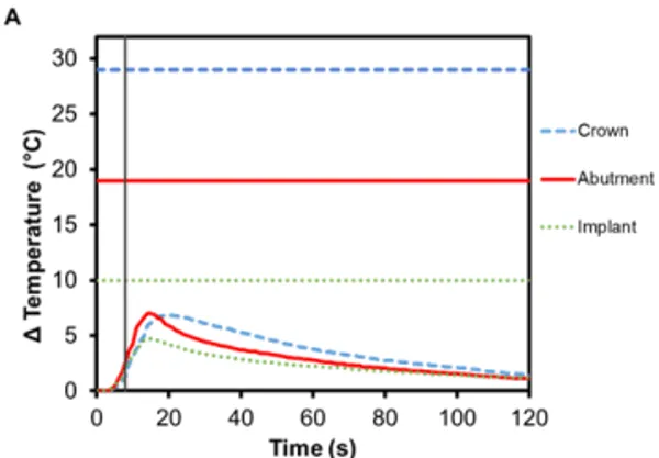
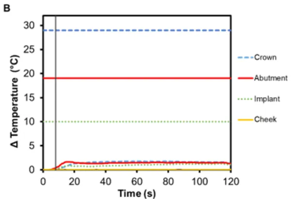
Figure 7. Change in temperature of (A) a cementable abutment restoration and (B) an adjacent OEM abutment restoration during activation of a neighboring RODO abutment assembly using Smilekey as a function of time, where time zero represents the onset of activation induction energy. The vertical line at 8 s represents the end of the activation. The horizontal lines indicate maximum allowable temperature increases for 1 s ≤ t < 10 s tissue contact times for both the crown and abutment, and over 1 min tissue contact time for the implant. During both the activation settings, the maximum temperature rise was less than the maximum allowable temperature for each component of the restoration.
Overall, the recorded temperature rise profiles were dependent on the material of each component. Titanium abutments heated the fastest in all the different configurations tested and experienced the greatest temperature rise during Smilekey activation. PFM crowns experienced higher temperature rises due to the highly-conductive, precious metal alloy used to fabricate the crown. In all cases, there was little temperature change measured in the implants – protecting surrounding anatomy from thermal injury. The results from this study are particularly relevant because the data was collected using a protocol consistent with the FDA-approved guidelines. It should be noted, however, that relative to a clinical, in vivo application, the values reported here were collected in vitro and should be considered as specific to the static, phantom model described above.